What is Survey Control and Why is it Needed?
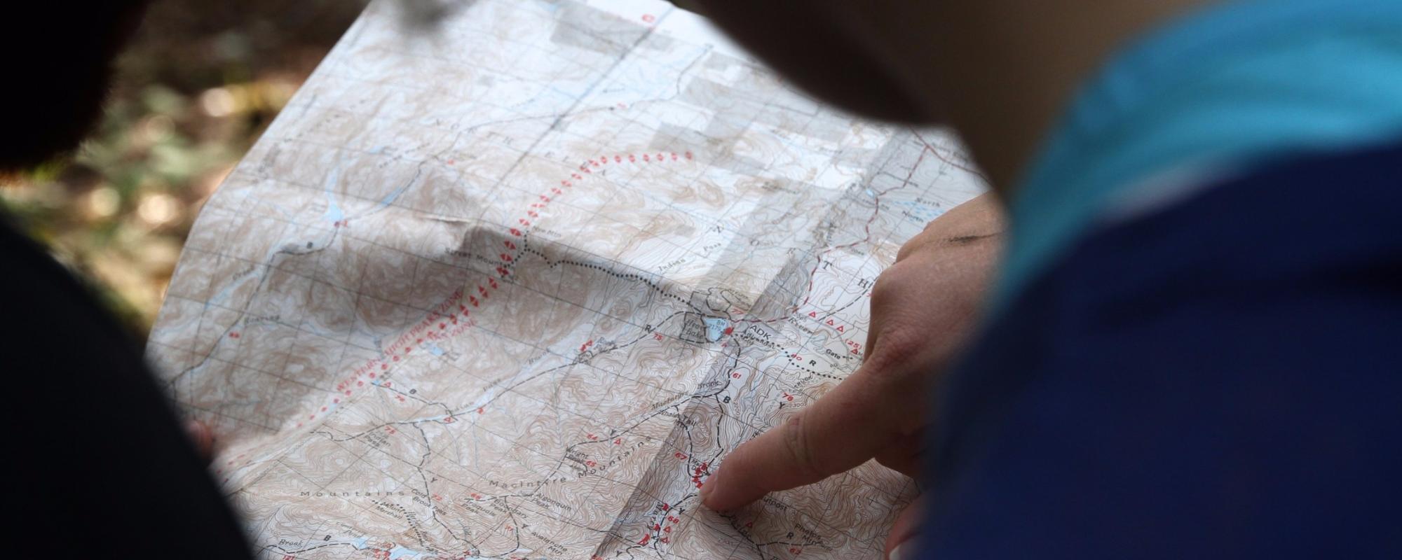
To be of practical use, the relationship between a map and the real world it represents must be clear and accurate. This means that the following information must be known:
- scale (the the relationship of distance on the map to distance in the real world);
- orientation (which way is North?) and;
- height.
To be able to do this, the mapmaker must know the position (latitude, longitude and height) of a selection of features that can be seen clearly on the map. These positions are known as the Survey Control.
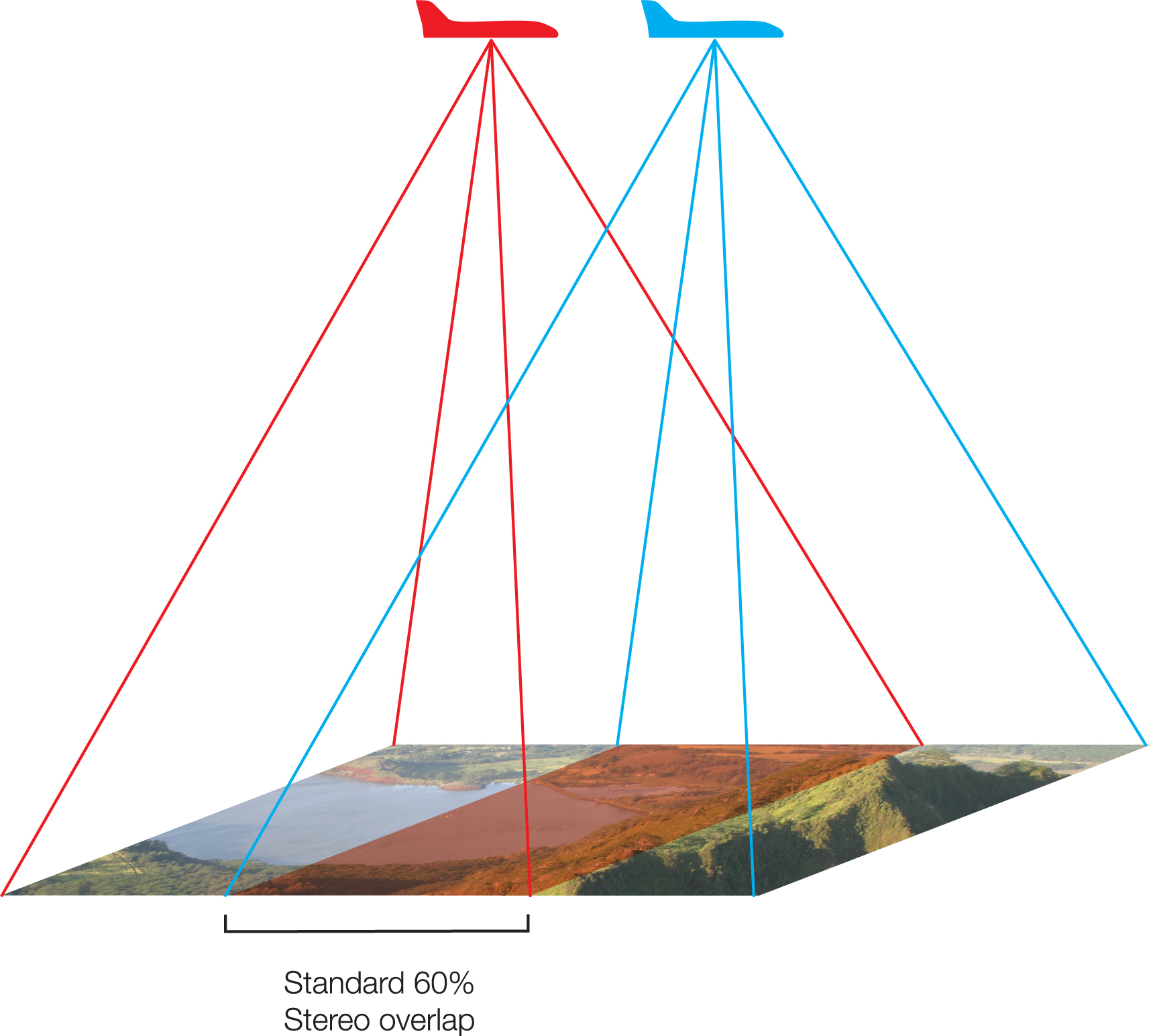
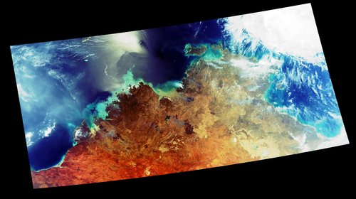
Modern maps are usually based on overlapping photographs taken from an aircraft (aerial photography) or digital images from a satellite (satellite imagery). In these cases the Survey Control not only scales and orients the map, it is also used to remove any distortions in the photograph/imagery.
How is the Survey Control Measured?
The surveying techniques used to calculate the positions of the Survey Control depend on the purpose and accuracy required for the map or project, but in every case they must start from a known position (Latitude, Longitude and Height). In the past this point may have been an isolated point (such as a hill) with its position calculated from astronomical observations. But these days, it is most likely to be part of a network of previously surveyed points.
Explaining Some Jargon – Astronomical Observations and Magnetic Bearing
Astronomical Observations

The position of the sun and stars at any time has been well documented in tables and formulae for many centuries. By observing vertical angles to the sun or stars and accurately noting the time of the observations, it is possible to calculate the observer’s position (Latitude and Longitude). Until recent times this method was used for navigation on moving ships and even aircraft, generally using a sextant to measure the angles. Similarly, using a theodolite on solid ground to measure the vertical angles gave starting positions for surveys.
By measuring horizontal angles between the sun or stars and a known reference point, it is also possible to calculate the orientation (angle from true north) of the reference point.
These techniques have generally been superseded by Global Positioning Systems (GPS).
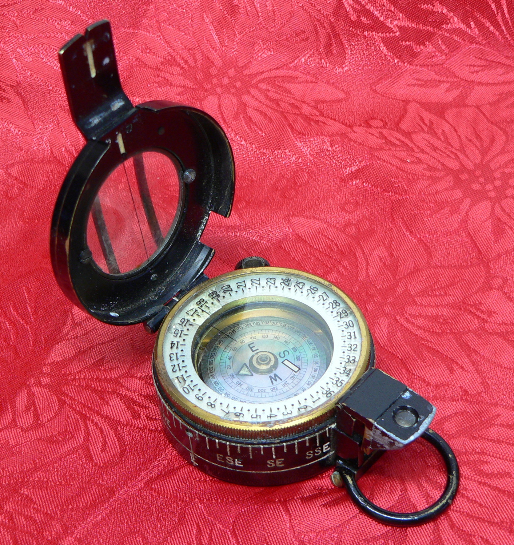
Magnetic Bearing
A Magnetic Bearing is the reading on a magnetic compass when sighting a landmark feature. It is the horizontal, clockwise angle between Magnetic North and the landmark feature.
Background
In times past, for the simplest types of maps, such as those a military officer might sketch when gathering information on the battlefield, visible landmarks (hills, buildings etc) would be fixed from his position by an estimate of the distances and the magnetic bearings to them. This would provide enough information to allow others to use the sketch map.
Similarly, to plot an unknown coastline, navigators such as Captain Cook, would have used magnetic bearings from the ship at several different locations, to the same visible landmarks on the shore (headlands, river mouths, mountain peaks, etc). The ship’s positions would have been known from previous observations to the sun and ⁄ or stars, and subsequent magnetic bearings, estimated speed and distance (known as dead reckoning).
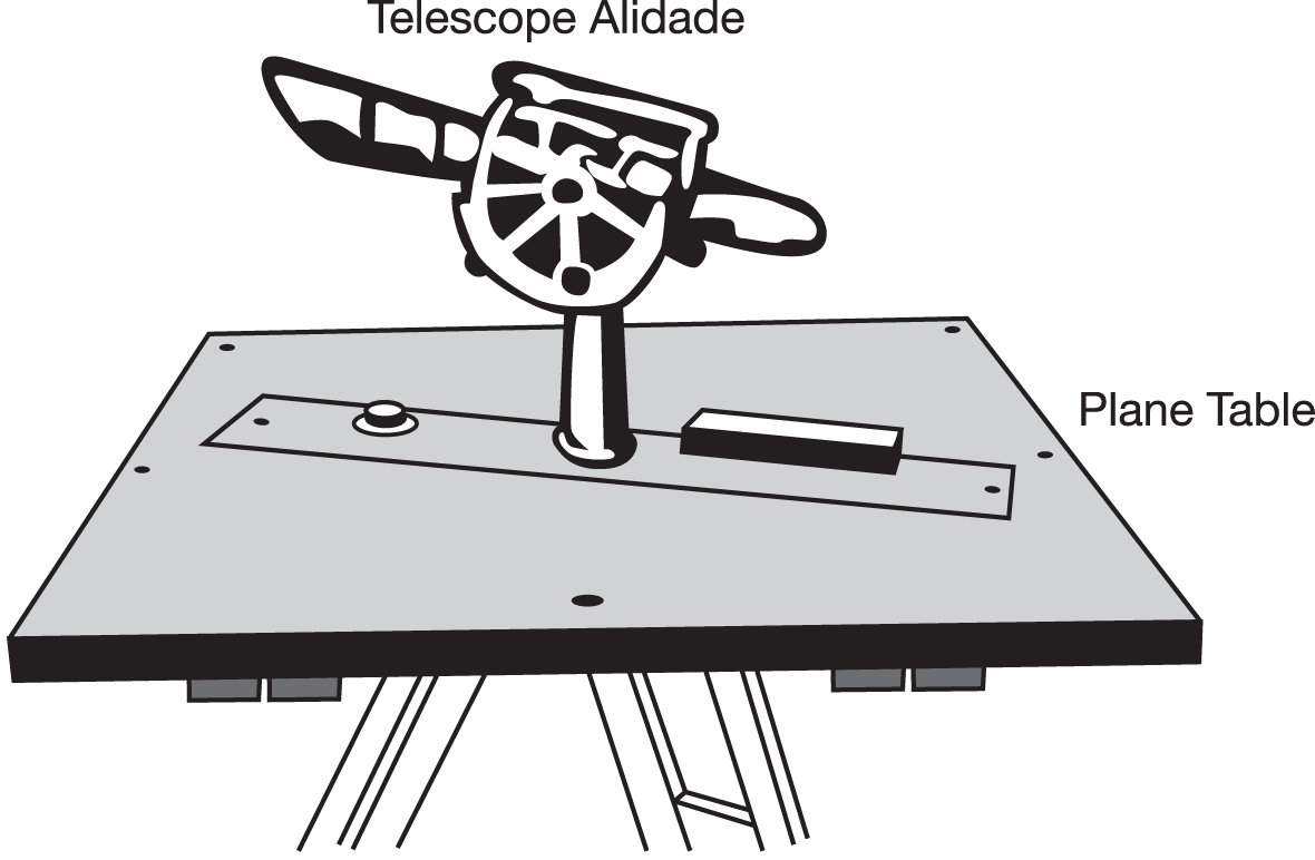
To directly map small areas, a more sophisticated version of the military officer’s sketch map could be made using a ‘plane table’. With this method, a sighting scope is pointed at known features and the lines to them plotted directly onto a sheet of paper (the map) which is fixed to a horizontal board (the ‘plane table’). When the same features are plotted from several known points (the Survey Control) the positions of the features are fixed by the intersecting lines.
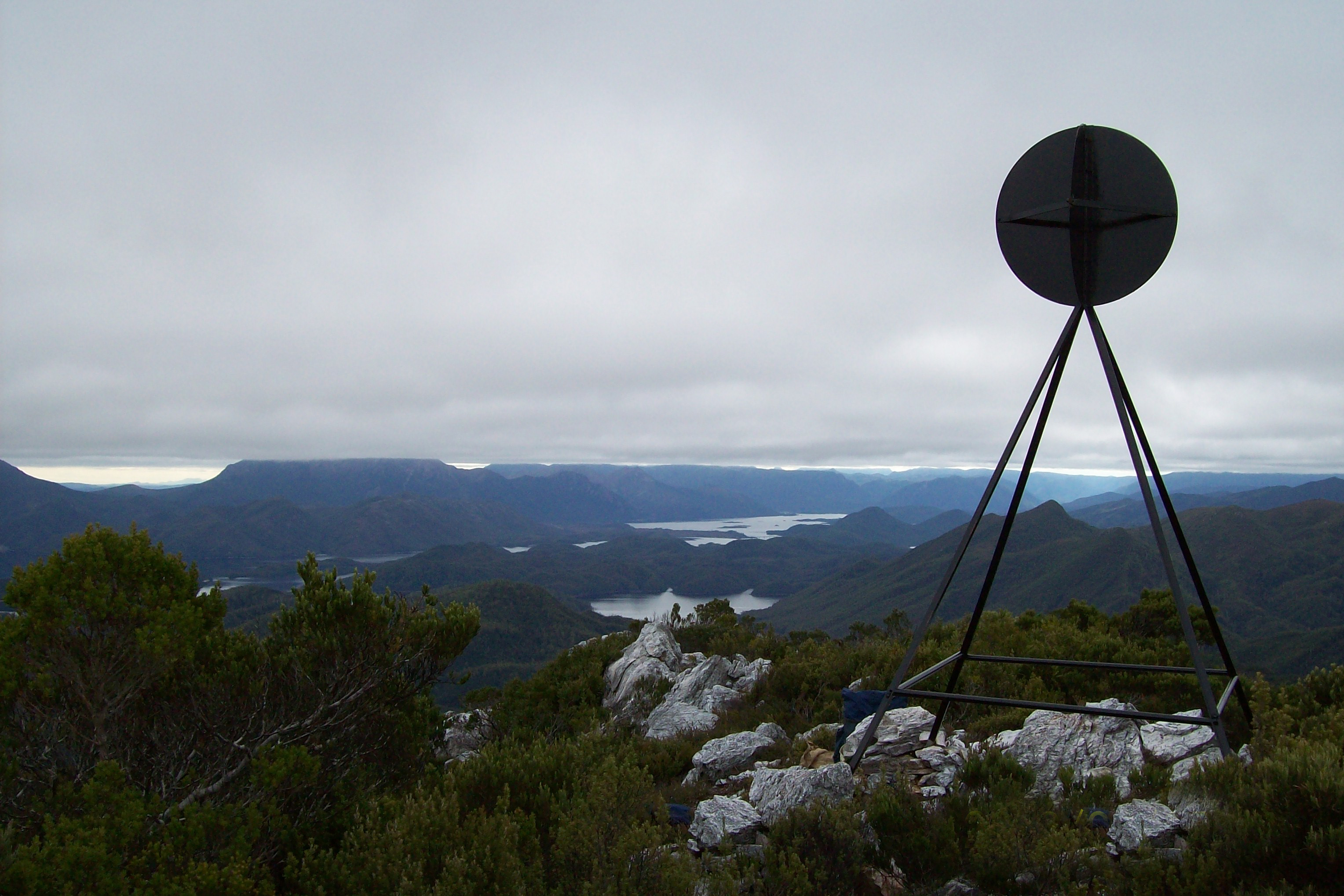
In an area without a survey control point, a starting point first needs to be established, usually by astronomical observations. Other survey control points are then determined by measuring to them from the starting point. Because you have to be able to see between the survey control they are usually on hilltops.
National Surveys
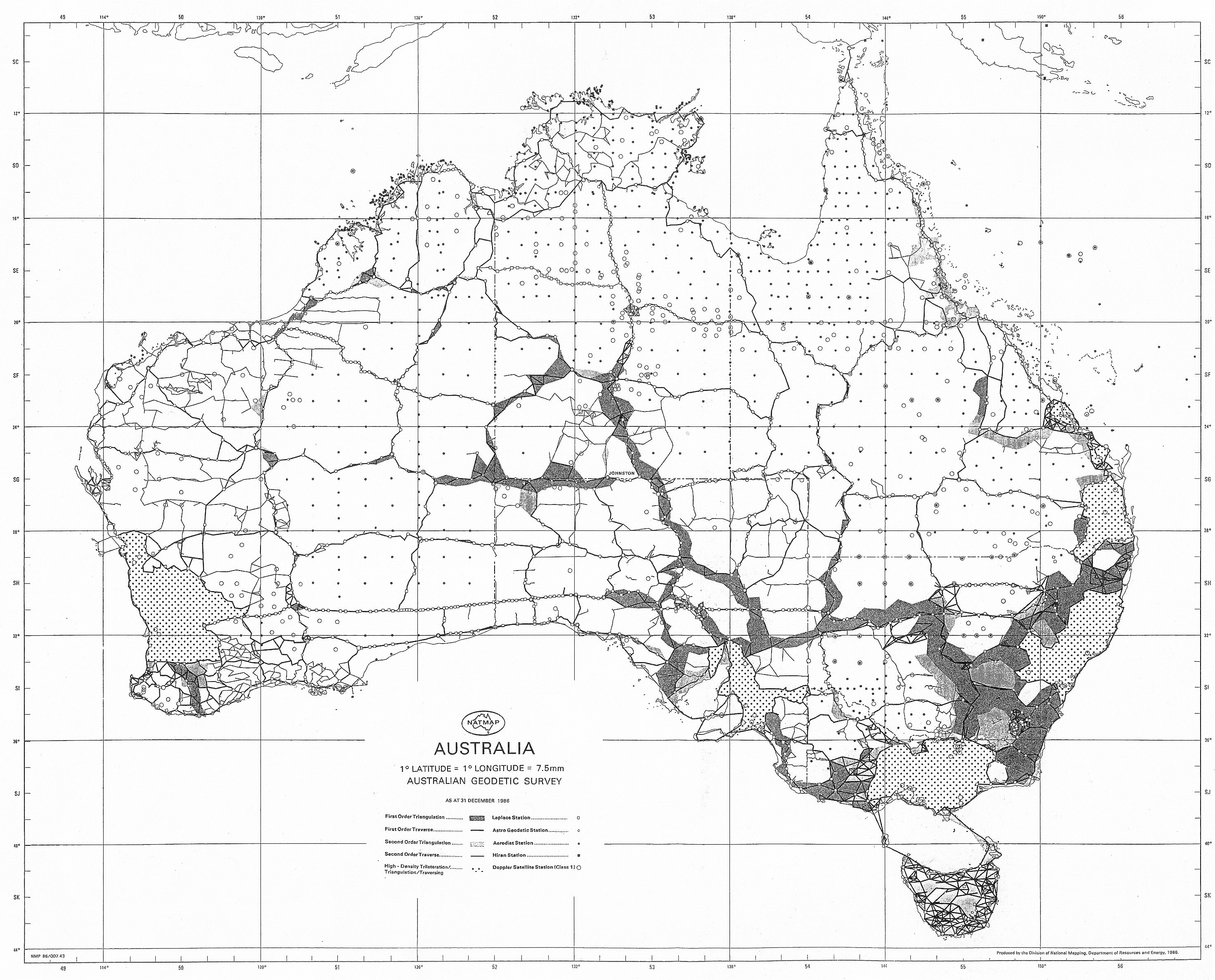
These days, most countries have an established network of accurate Survey Control measured from one or more datums. A network of surveying measurements then extends the positions to where they are needed. Traditionally, a sparse network of accurate Survey Control points (the primary or national network) is established to provide starting points for local surveys (the subsidiary or local networks). These in turn are used as the basis for surveys for particular projects, such as mapping control. The surveying methods used to produce the national and local Survey Control for a map, or any other project, depends on the terrain, the equipment available and the accuracy required.
Although traditionally made up of triangulation, trilateration and traversing networks, these days Surveying with Global Positioning Systems (GPS) is used to strengthen the traditional network and to independently provide additional survey control.
Explaining Some Jargon – Plane and Geodetic Surveying
When a survey is over a small area (e.g. with lines less than a kilometre) simple trigonometry can generally be used. This is known as ‘plane surveying’. Once the survey needs to allow for the curvature of the Earth (and other complex issues) more precautions are taken with the observations, and the calculations need to allow for (among other things) the curvature of the Earth. These are known as ‘geodetic surveys’.
Explaining Some Jargon – Trig Stations
The starting point or origin of a survey is sometimes called the ‘datum’ point, because it is the link to the datum used for the survey.
Hilltop survey marks are often referred to as ‘Trig Points’ or ‘Trig Stations’ because trigonometry is used to calculate their positions – their full title is Trigonometric Point or Station. They are permanently marked on the ground and usually have a beacon or cairn of rocks directly above them so they can be seen from a distance. Sometimes the Trig Station is an observation pillar on which the surveying instrument is placed – including theodolites, Electronic Distance Measuring devices (EDMs) and GPS antennas.